
In this case study we are going through the process of designing a database for storing the information contained in an input file for EPANET, software which can analyse water supply distribution networks.
The last post looked at the first two tables in our schema and gave examples of the data which could be stored in them.
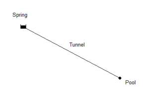
Now let’s look at how we define our network parts. Our simple example, Hezekiah’s tunnel (also known as the Siloam tunnel (https://en.wikipedia.org/ wiki/Siloam_tunnel)), has a spring at the start (https://en.wikipedia.org/ wiki/Gihon_Spring), a pool at the end (https://en.wikipedia.org/ wiki/Pool_of_Siloam), and a tunnel in between. Using EPANET, this is most simply modelled as a reservoir and a junction with a pipe between – as shown below.
As is standard for anything in engineering (and many other fields), the first thing we must choose is our units. This is very much the same as choosing the language we wish to write in. Translation between languages is possible, but the language used must be consistent. In Australia, we use metric units, and this makes the job of an engineer much easier. When I used to work as an engineer, I had to use imperial units at times, but it always felt as if the units added another level of complexity all by themselves. Throughout this example, I will try to provide both, but if I make a mistake with the imperial units, I hope you will be understanding.
The units to be used are specified in the [OPTIONS] section, but we will look at that section later.
The sections of the EPANET input file we need to work with now are all in the “Network Components” column and are bold in the table below.
| Network Components | System Operation | Water Quality | Options & Reporting |
|---|---|---|---|
| [TITLE] | [CURVES] | [QUALITY] | [OPTIONS] |
| [JUNCTIONS] | [PATTERNS] | [REACTIONS] | [TIMES] |
| [RESERVOIRS] | [ENERGY] | [SOURCES] | [REPORT] |
| [TANKS] | [STATUS] | [MIXING] | |
| [PIPES] | [CONTROLS] | ||
| [PUMPS] | [RULES] | ||
| [VALVES] | [DEMANDS] | ||
| [EMITTERS] |
For the spring, we need a [RESERVOIRS] section. Each line in the [RESERVOIRS] section describes one reservoir and must contain the following:
- ID label (up to 31 characters (letters and digits))
- Head (m/ft)
- Head pattern ID (optional)
For the tunnel, we need a [PIPES] section. Each line in the [PIPES] section describes one pipe and must contain the following:
- ID label (up to 31 characters (letters and digits))
- ID of start node
- ID of end node
- Length (m/ft)
- Diameter (mm/inches)
- Roughness coefficient
- Minor loss coefficient
- Status (OPEN, CLOSED, or CV)
For the pool into which the tunnel empties, we need a [JUNCTIONS] section. Each line in the [JUNCTIONS] section describes one junction and contains the following:
- ID label (up to 31 characters (letters and digits))
- Elevation (m/ft)
- Base demand flow (flow units) (optional)
- Demand pattern ID (optional)
To produce an input data file, we need some more information about our spring, tunnel and pool. Once we have that information, we can produce the input file, but we won’t stop there. We want to store this data in a database, so we will need to look at the tables and columns required to store the information not only from our specific input file, but for all EPANET input files in general.

Leave A Comment